Thursday, September 15, 2016

Important things to study

Curve fitting
- regression
- interpolation: Its is required in situation where we need to estimate peak of signal based on limited set of discrete values.
- Fourier approximation

Linear curve fitting: this kind of curve fitting introduces discontinuity in the curve
Polynomial curve fitting: removes discontinuity from the curve
Spline curve fitting:  sometimes polynomial curves make the curve fitting way too distorted by what is expected. In such scenarios spline is a better options. It behaves more like linear, but removes discontinuity from the curve.

Continuous wave Fourier transform
Discrete wave Fourier transform O(n^2)
Fast Fourier transform O(n. log2(n))

Why discrete FT required in practical applications?
--> Real life data is discrete. And DFT provided fast method of find frequency components. If Continuous FT is to be used, first interpolation is required to be done & then followed by CFT.

Why FFT is required is DFT is already there ?
--> FFT is even fast method of finding frequency content in the discrete data.

Where CFT is required practically?
--> Problems w


Significance of ROOT MEAN SQUARE: Its is derived from AC current. When AC current is passed through resistive load, the dissipate power will be same as the power dissipate when DC current of value equal to RMS of AC current is passed through same resistive load.

Mean
Variance
Standard deviation

IPC - POSIX Shared Memory

shmget() system call - create shared memory
shmat() system call - process that wish to access the shared memory  must attach it to their address space
shmdt() system call - when process no longer wish to access the shared memory, it can be detached from the address space using this call
shmctl() system  call - remove shared memory from system

Other processes that wish to access this shared memory must first attach to it using shmat()

---------------------------------------------------------------------------------------------
IPC_sharedmemory.c
---------------------------------------------------------------------------------------------


Wednesday, September 14, 2016

JTAG, SWD and debugWIRE: How are they different ? Its always a question ..... Let me clarify

JTAG - Joint Test Application Group
- Its used for verifying design and testing PCB after manufacturing
- Its referred as IEEE Standard 1149.1
- Standard Test Access Port and Boundary-Scan Architecture
- Programming and debugging both can be done using JTAG

Physical interface:

  1. TDI (Tets Data In)
  2. TDO (Test Data Out)
  3. TCK (Tets Clock)
  4. TMS (Test Mode Select)
  5. TRST (Test Reset)
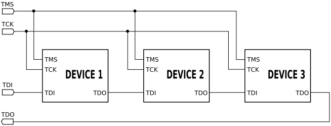
Daisy chain way of using JTAG

Example of JTAG chain


SWD - Serial Wire Debug

Serial Wire Debug (SWD) is debug port for microcontroller where package is small, or small number of pins.
Its used mostly in ARM architecture chips
SWD is availabel as a part of Core Sight Debug access port
Compatible with all ARM processors, and any processor that uses JTAG
- Programming and debugging both can be done using SWD
Physical interface: 
  1. SWCLK (Serial Wire Clock)
  2. SWDIO (Serial Wire Data In and Out)
In case when SWD is used for JTAG based process
  1. SWCLK --> TCK
  2. SWDIO --> TMS
With SWD protocol, the debugger is connected to AMBA bus as another master, using which debugger can access ARM core system and peripheral memory

NOTE:
Ofcourse, VCC and GND need to be common between In-Circuit-Debugger/Programmer and Processor

SWO (Serial wire out) wire is used sometimes along with SWCLK and SWDIO.
Some of the programmer and debuggers like STLINK provide debugging utility like printf(), which are very useful. These utilities use SWO wire to send serial data over it to PC. But here you need to set the system clock value correctly in the serial debug viewer configuration on PC.

debugWIRE

debug WIRE is a single wire interface provide in most Atmel AVR microcontrollers.
Its even more beneficial compared to JTAG and SWD as its very useful in places where package pin count is very small. On-Chip-Debugger (OCD) is provided on silicon itself by Atmel. dW single wire is internally connected to OCD. Whenever BREAK instruction (Software breakpooint) or (Hardware breakpoint) is observed by OCD, the CPU core operation is stopped and halted. All the SRAM, Peripheral register values, IO status information is sent by OCD over dW wire to the External Debugger unit(JTAGICE3). It will convert dW information to USB so that information could be sent to PC. On PC there will be a Debug software program which will grab the data and display it. Debug software running on PC will be a part of AtmelStudio.
- Only debugging both can be done using debugWIRE
- SPI interface is used for programming where dW debug interface is used


Physical interface:
Single wire dW.
Its a alternate functionality for RESET pin of the micro controller.

Microcontroller oscillator circuit working

 Circuit consists of two parts: an inverting amplifier that supplies a voltage gain and 180° phase shift and a frequency selective feedback path. The crystal combined with Cx and Cy form a tuned PI network that tends to stabilize the frequency and supply 180° phase shift feedback path. In steady state, this circuit has an overall loop gain equal to one and an overall phase shift that is an integer multiple of 360°. Upon being energized, the loop gain must be greater than one while the voltage at XTAL grows over multiple cycles. The voltage increases until the NAND gate amplifier saturates. At first glance, the thought of using a digital NAND gate as an analog amplifier is not logical, but this is how an oscillator circuit functions.


PROFILE

My photo
India
Design Engineer ( IFM Engineering Private Limited )

Followers