Memory access Architectures:
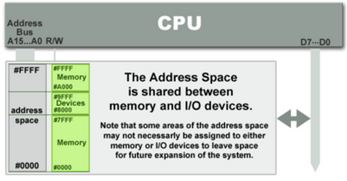
Code and data memory on same memory address map
Only one set of address and data bus shared for code, data memory
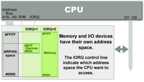
Code and data memory on separate memory address map
Two set of address and data bus, one for each memory
eg. 8051, PIC
1. Almost harvard
Code and data memory on separate memory address map.
But, instruction can be stored on data memory (like SRAM), or data can be stored on Code memory (like FLASH). For accessing data from code memory special instructions are provided.
eg. AVR8
2. Almost von-neumann
Code and data memory on same memory address map
But internal to CPU architecture there are separate instruction and data cache.
Depending on the coherency between the data and instruction cache there are two types:
a. With coherence (eg. x86, x64)
b. Without coherence (eg. ARM)
NOTE: Here in ARM architecture, there are possibility of problems with coherency. In order to avoid this the variables should be defined volatile as far as possible. This makes sure, after every operation the output is stored back to SRAM rather than just keeping it on cache and using it for next operation.
Interesting article for the explanation:
http://ithare.com/modified-harvard-architecture-clarifying-confusion/
CPU architecture:
8051is a harvard architecture. Good for small applications, but for big applications where data processing size requried is more. Number of vectored interrupts are less. Lack of memory management unit on chip.
Good for applications where lot of peripheral support required on silicon. It has very small stack memory.
Modified Harvard architecture for 8bit data processing. Good for small applications
Most advanced architecture with memory management, nest vectorred interrupt controller, debug and trace units with support for SWD and JTAG. Capable of operating at high frequencies.
Instruction sets:
- CISC - complex instruction set machine
Code size less
Pipelining cant be implemented
Time per instruction not the same.
- RISC - reduced instruction set machine
Code size more
Pipelining can be implemented
Time per instruction the same.
Instruction execution statictics are measured in DIPS(Dhrystone instructions per second) or MIPS (milion instruction per second)